5.1 Statetransition Diagram Links Description of events Download
State Transition Diagram The role of the state-transition diagram is to represent finite-state automata (i.e. entities that are characterized by a set of states which, at any given moment, are in a specific state) in the form of a set of transitions, which may or may not be labeled. From: Agent-based Spatial Simulation with Netlogo, 2015
Transition State Diagram Template Visme
In the state transition diagram, An object always remains in some state. Further, the state of the object may change after an event occur. Event Any activity that may trigger a state transition or can change the state. Guard In the state transition diagram, a guard is a boolean expression.
4 Statetransitions diagrams
The state transition diagram also illustrates the states and transitions of the communication protocol between the recipe phase and the equipment phase. The phase logic must adhere to the rules depicted in the state transition diagram. Only valid state transitions as depicted in Figure 8.6 may be utilized.
Objects Use Cases Actors State Transition Diagrams Chris Bell Riset
An alternative, or complementary, way is the use of state transition diagrams. This is the main topic of this chapter. We start in Sect. 13.1 with a brief review of finite state machines and their associated state transition diagrams. We then explain, in Sect. 13.2, how entities can be modeled as state machines, and that in this case state.
What is State Transition Diagrams?
State Transition Diagram are also known as Dynamic models. As the name suggests, it is a type of diagram that is used to represent different transition (changing) states of a System. It is generally used to graphically represent all possible transition states a system can have and model such systems.
State Transition Diagram (STD) actions of the attacker only (no
State Transition Diagrams (STDs) are used along with specifications to define the functional detail for a system. Unlike data processes, control processes have a specialised role: enforcing sequencing over environmental control stimuli to the system, and the internal operation of the system.

FSM for a simple machine tool The State Transition Diagram (STD) is a
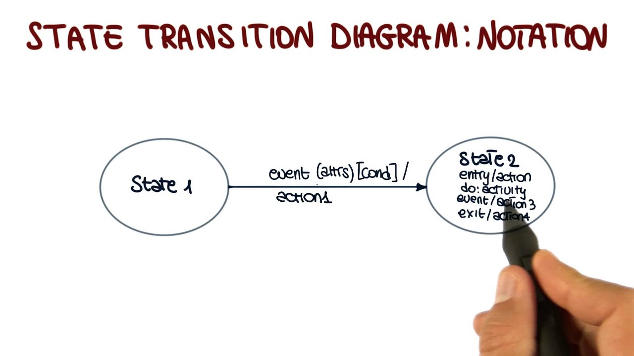
State Transition Diagram (STD) state. State transition . Basic Elements. State = set of values that describe an object (its condition/situation) at a specific moment in time {State is determined based on the attribute values} State transition = relationship indicating a state change {atomic (i.e. non-interruptible)} Previous slide:

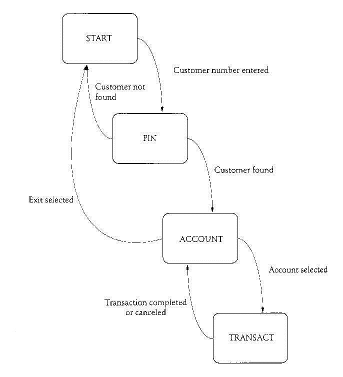
State Transition Diagram for an ATM System
State Transition diagrams describe the logical transition of a system through various states of operation by representing states, the transitions that connect them, and the events that trigger transitions. The implementation aligns with the SysML representation. The State Transition diagram is available for entities in the State class.
State Transition Diagrams Download Scientific Diagram
The semantics of state transition diagrams defined by translating the abstract syntax into timed port automata and to timed input/output relations on streams.. we introduce a graphic specification technique, called state transition diagrams (STD), and show the application to the feature interaction problem. Using a stream-based formal.
state transition diagram software engineering YouTube
MIT 6.004 Computation Structures, Spring 2017Instructor: Chris TermanView the complete course: https://ocw.mit.edu/6-004S17YouTube Playlist: https://www.yout.
ECU State Transition Diagram
of the State Transition Diagram (STD) with a few interesting wrinkles. However, the notation for FSMs in UML also includes elements of flow charts and Petri-nets. It is one of the most complete FSM notations every gathered into a single notation. We'll be looking at those other facets of FSM notation in subsequent articles.
State transition diagram. Download Scientific Diagram
This video covers all information about State Transition Diagram in software engineering with example 👉Subscribe to our new channel: https://www.youtube.c.
PPT State Transition Diagrams PowerPoint Presentation, free download
State Transition Diagram When representing the requirements for a system, all views of required behavior need to be considered. A system can operate in different modes, often referred to as states. Different system states are triggered by specific events that initiate a transition to another state.
SimpleFresh STD (State Transition Diagram)
State Transition Testing is a black box testing technique in which changes made in input conditions cause state changes or output changes in the Application under Test (AUT). State transition testing helps to analyze behaviour of an application for different input conditions.
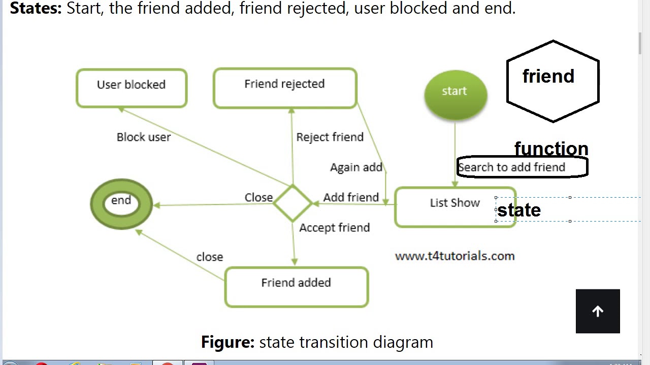
Examples of State Transition Diagrams
Section 2 introduces state-transition diagrams and provides example diagrams. Section 3 lists some online resources that you or your learners may find useful, including software packages for creating state-transition diagrams. Section 4 gives ideas for class and homework activities.
State transition diagram for CSMA/CA Download Scientific Diagram
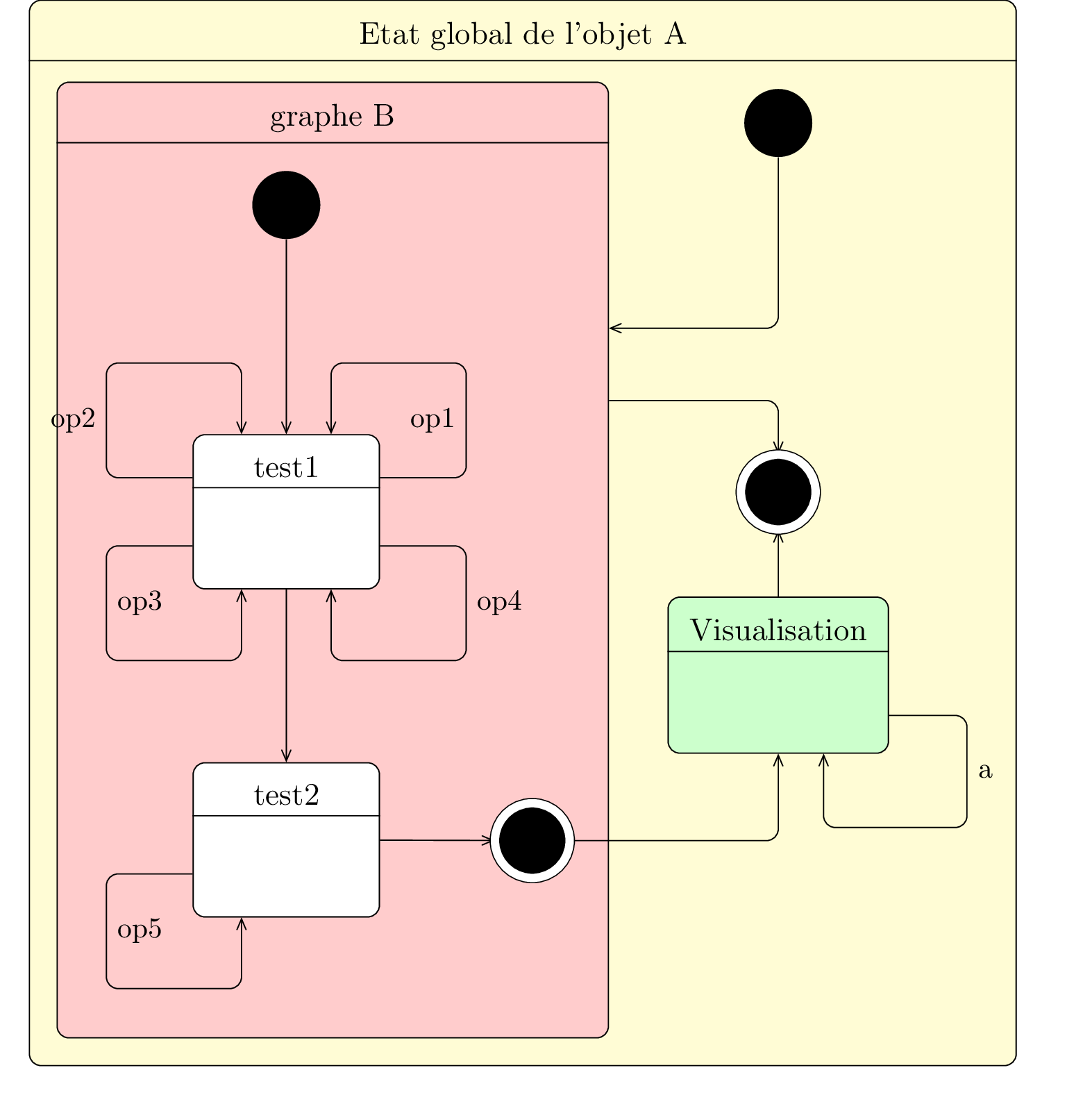
A state diagram consists of states, transitions, events, and activities. You use state diagrams to illustrate the dynamic view of a system. They are especially important in modeling the behavior of an interface, class, or collaboration.